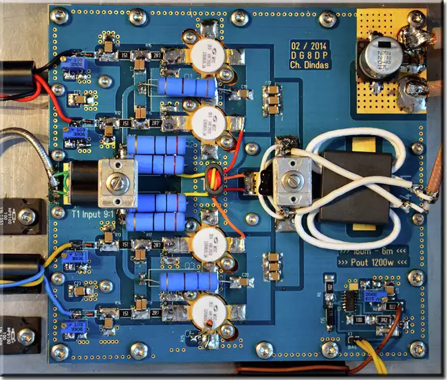
PA Module
PA module
One thing in advance, I have not reinvented the circuit. Because like most commercial power amplifiers also my power amplifier uses the parallel push / pull technology which was already introduced in the 80s by Helge Granberg, developer at Motorola and author. Helge Granberg developed a developer board with 4x MRF150 which delivered a good 600W. This board was actually not intended as a PA module, but was copied umpteen times.
I developed a new PCB layout, where of course the symmetry was very important and the choice of components. Since I did not want a huge Unun in the output, this was now built as a Transmissen Line Transformer (TLT). It was important to me that the module runs stable, is robust, generates clean signals and reaches a high efficiency to dissipate as little heat as possible.
I wanted to avoid design errors like Tokyo High Power. These reduced the gate decoupling resistors to only 0.25 ohms, which is absolutely too little. Although these power amplifiers can reach up to 6m, they like to start oscillating and in a few ms the MOSFETS are gone. A gate decoupling below 2 ohms I consider dangerous.
The PA module can be operated between 40 VDC and 52 VDC. It achieves with 4x Microsemi VRF2933 an output power of typ. 1200W CW on all bands from 160m to 10m. The BIAS supply voltage is temperature compensated via a NTC directly on a VRF2933, by the way the temperature is also measured there for the display and protection circuit. The BIAS current is adjustable via 4x 20 speed spindle trimmers. About the BIAS voltages you get an overview in the voltages menu how well the MOSFETS fit together. I recommend to use matched pairs. The measurement can be done easily or you can buy matched pairs.

Last version, 1200 W CW
